
Chapter 5: CASE STUDY- HERSHEY CHILDREN’S HOSPITAL
This chapter introduces the healthcare case study used for data collection, development and evaluation of the procedure for rapidly developing an Experience-based virtual prototype. The first part of the chapter introduces the case study, lays out the program requirements for the healthcare facility, the project description, status and context of the facility. The next section discusses the research approach and presents the timeline of the case study. The research approach includes the strategy for data collection and briefly describes the procedure for development, validation as well as evaluation of the EVPS along with a time line that shows when and how the process occurs.
5.1 CASE STUDY DESCRIPTION
The new Penn State Milton S. Hershey Medical Center Children’s Hospital is a 263,000- square-foot, five-story facility that is expected to open by end of December 2012. The state of the art facility is currently under construction and the hospital personnel are gearing up for transition planning. The new hospital is an independent facility adjoining the main hospital and the Hershey Cancer Institute. At present, the Children’s Hospital is located on the seventh floor of the main hospital.
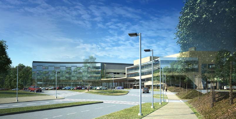 Figure 5-1. Rendering of the new Hershey Children’s Hospital (Source: Payette Architects).
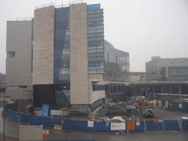
| Architect: | Payette |
| Construction Manager: | L. F. Driscoll |
| Delivery Method: | CM @ Risk |
| Area: | 263,000 square feet |
| Cost: | $207 Million |
5.2 CASE STUDY APPROACH
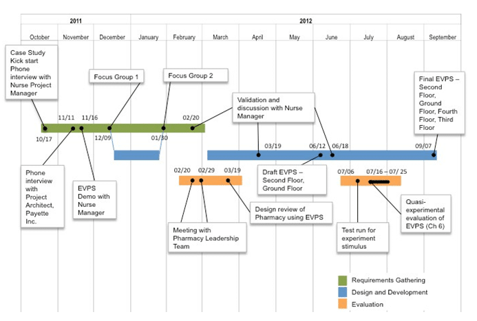 Figure 5-3. Timeline for Hershey Children’s Hospital case study.
5.3 FOCUS GROUPS
5.3.1 First Focus Group – December 9, 2011
At the start of the first meeting, the researcher and facilitators welcomed participants, discussed the agenda and went through a round of introductions. The researcher presented a few slides outlining the background of the research project and outlined some goals for the meeting. Participants were shown two concept videos of the experience-based virtual prototypes; the first video showed scenarios of activities that can be performed in virtual prototypes and the second video showed the level of realism that can be achieved through use of lighting and textures. Focus groups were used to obtain data for identifying scenarios of tasks and spaces that need to be developed in the virtual prototype. Participants were split into groups of 4 to 5 so that they could discuss amongst themselves and provide feedback. Each mini group was required to discuss and work hands-on to help answer research questions.
5.3.2 Data Collection
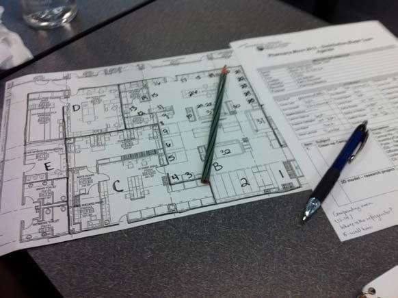
Large 42” X 30” printouts of floor plans from levels 1-5 were used as artifacts during the focus group discussion along with the use of post-it notes to enable the participants to give feedback and answer the focus group questions. Questions asked during the meeting explored three broad themes (shown in Table 5-2) that focused on identifying and prioritizing the spaces, identifying and documenting scenarios and finally identifying modeling requirements for the development of the virtual prototypes. Table 5-2. List of questions asked during focus group 1.
| Theme I. Identifying and Prioritizing Spaces |
| 1. What do you see as the primary purpose of using the Experience-based Virtual prototyping System (EVPS) for your facility and why? |
| 2. Referencing the floor plans of the new Children’s Hospital, identify the spaces of highest priority that should be developed as interactive virtual prototypes using the EVPS. E.g., Pharmacy, Nurse’s station to patient rooms, route between Blood bank to OR |
| Theme II. Investigating and documenting scenarios |
| 3. What are the typical scenarios of activities that will take place within each space/ zone identified? |
| 4. Identify typical routes that will be taken by the staff in the hospital with the brief description of their purpose. |
| Theme III. Identifying design requirements for the EVPS |
| 5. What would be ideal level of detail that you would like in the virtual prototypes? Especially with regard to the following: |
| – Textures and colors (highly realistic to abstract) |
| -Lighting (Highly realistic to absent) |
| – Interactive objects (E.g., doors that open, crash carts that move) |
| 6. Which of the following features would you like to see in the EVPS for a particular space: |
| – Minimap |
| – Scenario menu |
| – Avatars (E.g., Nurses, Physicians, Facility managers, patients) |
| – Moveable objects (E.g., crash carts, wheelchairs, beds etc.) |
| 7. What additional features would you like to see in the EVPS? |
| 8. Is there any additional content that you would like modeled in the facility? |
Based on the questions asked, participants were instructed to note down their ideas and answers on post-it notes. The post-it notes were color-coded based on: end-users (blue), scenarios (green), tasks (yellow), spaces (pink) and objects or elements (purple) required for modeling the hospital. Participants reviewed different floor plans of the hospital where they marked spaces they considered important enough to be included in the EVPS and wrote them on post it notes (Figure 5-4). Similarly different colored post-it notes were used to get brief descriptions of scenarios, tasks and level of detail required.
. 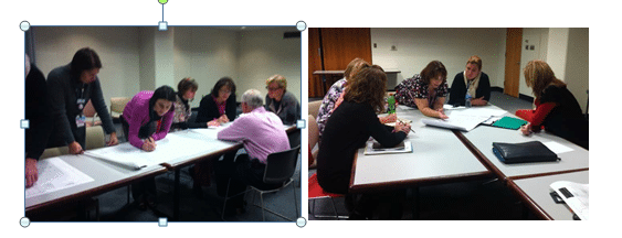
Figure 5-4. Data Collection during Focus Group 1.
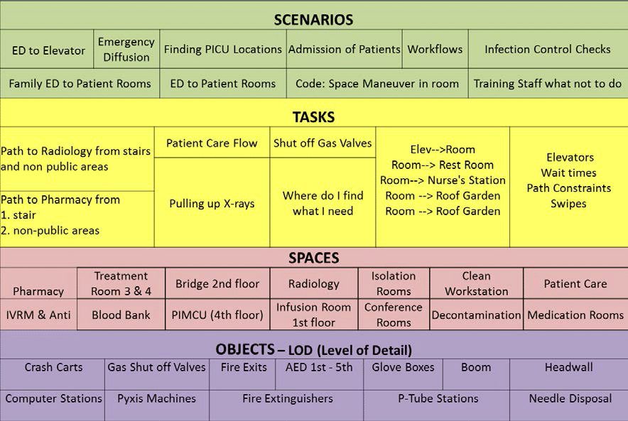
After collecting the post-it notes from participants (Figure 5-5), they were organized on a white board. Questions and clarifications helped reorganize and match different spaces of the hospital with certain scenarios of tasks. 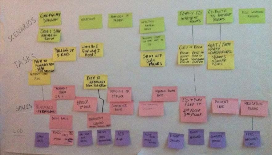 Figure 5-5. Color-code post-it notes with end-user scenarios.
- Clinical Care Documentation Center – This area is centrally positioned to be in proximity with the maximum number of patient rooms and is used by nurses for documentation.
- Patient Isolation Room with Dialysis – this room is chosen because it is used for patients with more complex conditions and because it has surgical boom equipment and an anteroom. The rationale to choose this room over others was to get nurses more familiar with one of the most complex rooms in the hospital.
- Treatment Room – Although the entire second floor is dedicated to having operating rooms, it was decided to have one treatment room per department for patients that could be easily accessible and also appear to be a pain-free area for children being treated. The treatment room has an examination table and head wall for medical air, vacuum and gases.
- Clean Supply Room – This room generally has storage of medical supplies and medication stored in shelves or automated dispensing cabinets like the “Pyxis” medication machines.
- Medication Preparation Room – This room is used for distribution of medicine to the patients and is close to the nurse’s station. It contains a work counter for preparation of medication, refrigerator, sink for hand washing and locked storage cabinets for biological medication and drugs.
- Soiled Utility Lab- This room is unique as it has the eye wash station and a laundry chute. It was deemed important to include this room in the EVPS so that nurses could familiarize themselves with the work process and know how to locate the room.
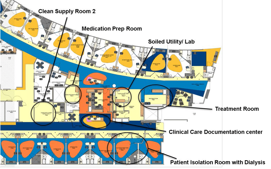 Figure 5-7. Spaces identified on the fourth floor for draft EVPS development.
Apart from a part of fourth floor with the above areas, the main pharmacy of the hospital located in the ground floor of the hospital was also identified as a space for possible inclusion in the draft EVPS.
5.3.3 Participants
| Role | Department | Dec 11 | Jan 12 |
| Nursing Project Manager | Children’s Hospital Support | 1 | 1 |
| Residency ProgramDirector | Pediatrics | 1 | |
| Residency AssistantProgram Director | Pediatrics | 1 | |
| Physician | PICU (Pediatric Intensive Care Unit)Senior resident | 2 | |
| Director of Nursing | Nursing Pediatrics | 1 | 1 |
| Operations Director | Children’s Hospital Administration | 1 | |
| Leadership team | Pediatric Acute Care and Hematology/ Oncology | 2 | 3 |
| Clinical Nurse Educator | NEPD (Nursing Education and Professional Development) | 1 | 1 |
| Nurse Manager | OR (Operating Room) | 1 | |
| NICU (Neonatal Intensive Care Unit) | 1 | ||
| PICU/ PIMCU (Pediatric Intensive/ Intermediate Care Unit) | 1 | 1 | |
| Perianethesia (nursing for patients undergoing anesthesia) | 1 | ||
| Float Pool /Per Diem/ NVAT (Nursing Vascular Access Team) | 1 | ||
| Patient Transport | 1 | 1 | |
| Clinical Head Nurse | PICU/PIMCUPerianesthesia | 1 | 2 |
| Manager | Child Life | 1 | 1 |
| Coordinator | Family Services | 1 | |
| Pharmacy staff | Pharmacy | 1 | 1 |
| Senior Technologist | Radiology | 1 | 1 |
| IC Coordinator | Infection Control | 1 | |
| Environment Health MgrFire protection Engineer | Safety | 1 | 1 |
| 17 | 20 |
During the second focus group meeting, draft EVPS of the Children’s Hospital with interactive virtual prototypes of the fourth floor with varying levels of detail and the pharmacy were distributed to the participants. The goal of this meeting was to enable the participants to experience first-hand and interact with the EVPS model and then brainstorm ideas and goals for the next iteration of development of the EVPS.
5.3.5 Potential Use of EVPS at Hershey Children’s Hospital
During focus groups discussions, participants envisioned using the EVPS for purposes of educating and providing a level of comfort for way finding to the entire hospital staff and possibly to patients and their families in the future. Apart from reviewing the design of the new facility, the hospital staff and project team envisioned using the EVPS in the transition process.
5.4.1 Scenarios based on End-Users
As a first step of requirements analysis, participants were asked to identify who they envisioned to be the ultimate end-users of the EVPS. End-users identified to use the Children’s Hospital EVPS application can be broadly classified into three categories of patients, families and staff. Table 5-4 shows a list of potential end-users identified for using the EVPS application.
Table 5-4. List of potential healthcare facility end-users who could use the EVPS. Healthcare Facility Users Patients Families. 
Within staff of the hospital, various categories were identified that included physicians, residents, surgical technologists and OR aides. Apart from majority of the staff, which is nursing, other staff included transport, anesthesia techs, and respiratory therapists. The nursing category was further divided into different type of nurses based on the specific duties they performed. While patients and their families were considered the most important potential users for the application, it was decided that based on the time requirements and knowing that this would be an internal pilot study, it was considered more appropriate to test the application with nurses. Content analysis using frequency of word count on the end-users of the twenty-three scenarios revealed the highest count for nurses (Figure 5-8). The next highest word frequency is for family followed by all staff. Other frequently occurring end-users are patients, transporters, physicians and pharmacy staff. 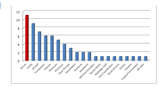 Figure 5-8. Users identified for scenarios during second focus group meeting.
| Sole mention | First mention | Second mention | Third mention | |
| Nursing staff | 3 | 5 | 2 | |
| Staff | 2 | 4 | 2 | |
| Transport staff | 2 | 1 | 2 | |
| Pharmacy | 2 | 1 | ||
| Patients and families | 1 | 1 | 6 | |
| OR staff | 1 | |||
| Physicians | 2 | 2 | ||
| Respiratory | I | 2 | ||
| Radiology | 2 | |||
| Other | 3 |
Next the scenarios were categorized based on themes starting from types of scenarios, scale of scenarios and level of detail required to implement the scenarios.
5.4.2 Scenario Categories
The first theme of identifying and categorizing scenarios was based on the matrix developed in Chapter 4. The scenarios are mapped on the spectrum of varying levels of detail on x-axis against the end-users of scenarios identified on y-axis (Figure 5-9). Scenarios identified are classified based on way finding or movement-based, process-based (combination of way finding and set of less detailed tasks), spatial organization and finally detailed task-based scenarios. Figure 5-9. Mapping scenarios based on category and users.
5.4.3 Scenarios based on Spaces
The next analysis of scenarios was done based on word frequency of spaces mentioned by participants in the scenarios (Figure 5-10). As most scenarios are concerned with way finding, pathways, hallways and elevators were in large numbers.
|
SECOND FLOOR Registration OR Pre-op |
1 | 4 | 5 | 12 | ||||||||
|
PACU |
5 | |||||||||||
| Nurse’s station | 10 | |||||||||||
| Charting area | 3 | |||||||||||
| Medication room/ supplies | 6 | |||||||||||
| Cleaned utility/ med pyxis room | 4 | |||||||||||
| Soiled utility | 3 | |||||||||||
| Code cart | 1 | |||||||||||
| Leadership offices | 3 | |||||||||||
| Storage – linen | 2 | |||||||||||
|
Lobby |
1 | |||||||||||
| Pathways/ hallways | 10 | |||||||||||
|
Elevator |
11 | |||||||||||
| Emergency areas | 4 | |||||||||||
| GROUND FLOOR | 5 | |||||||||||
| Radiology | 6 | |||||||||||
| Blood bank | 2 | |||||||||||
| Pharmacy | 7 | |||||||||||
| Patient room | 8 | |||||||||||
| Isolation room | 3 | |||||||||||
| Anteroom | 1 | |||||||||||
| Treatment Room | 3 | |||||||||||
| Family waiting | 4 | |||||||||||
| Play room | 2 | |||||||||||
| Restroom | 4 | |||||||||||
| Staff lounge/ Breakroom | 6 | |||||||||||
| Resident lounge | 1 | |||||||||||
| FOURTH FLOOR | 3 | |||||||||||
|
PICU |
3 | |||||||||||
|
PIMCU |
4 | |||||||||||
| THIRD FLOOR | 3 | |||||||||||
| Acute care | 1 | |||||||||||
| Oncology | 1 | |||||||||||
| Main lobby | 2 | |||||||||||
|
ED |
3 |
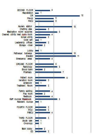 Figure 5-10. Spaces identified for EVPS development.
5.4.4 Validation of Scenarios
arms, booms and operating tables are required and curtains in PACU as they are not in the Revit model. Similarly, computer stations for nurses provided outside the patient rooms to enable nurses to chart and monitor the patients in the room are required. Lastly Pyxis machines in medication and supply rooms were also identified. 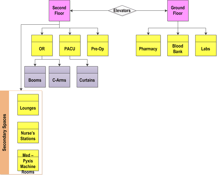 Figure 5-11. Spaces identified for development in Second Floor and Ground Floor.
5.4 EVPS DEVELOPMENT STRATEGY
Based on the requirements analysis done on the data collected through focus groups and interviews, a list of features was developed and storyboarding was used to develop concepts for the EVPS. Although many more interactivity features could be added the scope was restricted based on the envisioned end goal of the prototype as well as the time and resources available to develop it.
Since the project was in construction phase, the Revit model used for the development of the virtual prototype was highly detailed. Based on the requirements, it was ensured that only the required architectural elements are included in the model. Some furniture and equipment model content not included in the model was added. Missing model content comprised of patient beds in all patient rooms, examination and operating tables in the treatment rooms and ORs. Other model content added included pyxis machines, booms, chairs for nursing and charting stations and other equipment identified during requirements analysis.
5.4.2 Level of realism
Due to the size of the models and the focus on way finding scenarios, the level of realism in textures required was relatively low in the virtual prototypes. However care was taken to incorporate the color schemes of the flooring, which was one of the main design features of the Hershey Children’s Hospital and used as an aid to way finding by the architects. Some of the important equipment identified in requirements analysis were colored red for easy identification in the virtual prototype. These included fire extinguishers, elevators, and pneumatic tube stations for blood or medication transport near the nurse’s station.
5.4.3 User Interface
End-users were provided with options to go to the main menu, select another floor to navigate in, get instructions on how to navigate the model, turn the mini-map on or off, and select a space / department within the floor to navigate in, or quit the application. On quitting the application, the Hershey Children’s Hospital web page opened in the user’s browser.
The storyboards helped design the menu of the Children’s Hospital EVPS. The opening screen of the EVPS was designed to show a rendering of the hospital and give options to the user to select the floor that they wished to navigate. The hospital was broken down into the four floors for EVPS development- Ground Floor, Second Floor, Third Floor and Fourth Floor. On selecting any of the floors, the user was shown another screen with a schematic plan of the floor depicting locations of major areas or departments on that floor. Figure 5-12 shows a snapshot of the menu developed for the Second Floor EVPS. The user could then select any space and start navigating the interactive 3D virtual prototype of that floor.
5.4.3.2 Mini-map
The mini-map was considered an essential element in the prototypes, as the main goal was to use the model for way finding purposes (Figure 5-13). A red arrow head was added in the controller object hierarchy that was visible in the mini-map indicating and updating in real-time, the location of the user and direction of where they are heading within the facility.
5.4.4 Interactive Objects
The developed EVPS enabled users to retrieve information such as names of different equipment throughout the hospital floors by clicking on the objects. Also similar to hospital hallways with motion sensor activated doors, the prototype simulated doors to swing open using triggers and animated door objects. Figure 5-13 shows the Unity game engine interface during EVPS development. 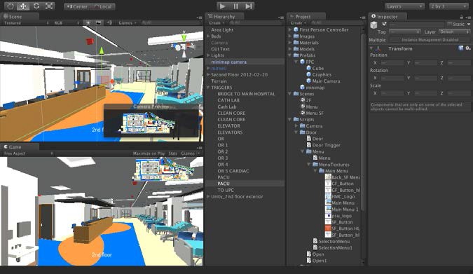 Figure 5-13. Space trigger objects and mini-map camera in the second floor EVPS.
Trigger objects were placed in various departments or areas of interest throughout the hospital floors such that while navigating, when the user entered specific spaces, text was displayed on the screen to indicate the name and other information on the space entered. Another interactive feature included buttons on the user interface that allows the user to click on the names of certain spaces. Once selected the controller object instantiates in that space allowing the user to begin navigation from there.
5.4.5 Challenges in Development
Polytrans was used to further optimize the model content before transferring it to Unity game engine. It was decided to split the different floors and develop them as separate Unity projects to ensure smoother visualization. However, some of the interactive objects such as clicking on6. Type and number of doors in the second floor of the hospital.
|
DOOR NAME |
Type | Count |
| Door Double Wrap Double Opposing Type G 84″ x 84″ | 1 |
3 |
| Door Double Wrap Double Opposing Type V 84″ x 84″ | 1 |
4 |
| Door Double Wrap Type F | 4 |
12 |
| 48″ x 84″ | 1 |
2 |
| 56″ x 84″ | 1 |
5 |
| 60″ x 84″ | 1 |
3 |
| 84″ x 84″ | 1 |
2 |
| Door Double Wrap Type G 84″ x 84″ | 1 |
3 |
| Door Double Wrap Type V | 2 |
3 |
| 72″ x 84″ | 1 |
2 |
| 84″ x 84″ | 1 |
1 |
| Door Single Wrap Double Acting Type F 36″ x 84″ | 1 |
2 |
| Door Single Wrap Double Acting Type G 36″ x 84″ | 1 |
7 |
| Door Single Wrap Side Light Type FG 36″ x 84″ | 1 |
1 |
| Door Single Wrap Type F | 3 |
22 |
| 36″ x 84″ | 1 |
18 |
| 42″ x 84″ | 1 |
2 |
| 48″ x 84″ | 1 |
2 |
| Door Single Wrap Type FV | 2 |
9 |
| 36″ x 84″ | 1 |
8 |
| 42″ x 84″ | 1 |
1 |
| Door Single Wrap Type G | 2 |
9 |
| 36″ x 84″ | 1 |
8 |
| 48″ x 84″ | 1 |
1 |
| Door Single Wrap Type V | 3 |
39 |
| 36″ x 84″ | 1 |
16 |
| 42″ x 84″ | 1 |
13 |
| 48″ x 84″ | 1 |
10 |
| Door Uneven Wrap Rev Type F 48″ (12 x 36) x 84″ | 1 |
2 |
| Door Uneven Wrap Type S 66″ (18 x 48) x 84″ | 1 |
12 |
| Cased Opening Wrap 36″ x 84″ | 1 |
1 |
| Overhead rolling 11′ x 21′ | 1 |
1 |
| Grand Total | 26 | 130 |
The door object appears as a single object including the frame in the Unity game engine. Using either 3ds max or Revit, each door was split into separate frame and door panel objects; animation was applied to the door panel based on if the swing was clockwise or anticlockwise and a door trigger object was applied. Finally the door was taken to the desired location. There were many approaches to do this and prefabs in Unity enabled efficient and repeatable use of multiple doors once they were animated. Other interactive objects that were not implemented included arrows depicting the route to get from point A to B within a hospital floor. The draft virtual prototype fourth floor showed a scenario where the user could click on a specific space they would like to go to and the user interface displayed arrows depicting the route to take. However, in the full hospital floor virtual prototype implementation, there were far too many route options that could not be covered using this approach. An alternate method of clicking the name of the space and instantiating the controller object in that location was adopted instead.
5.5 PHARMACY DESIGN REVIEW
As per the plans of the Children’s Hospital, the main pharmacy serving the entire Hershey Medical Center was being relocated in the ground floor where all the pharmacy staff would be consolidated. The footprint of the pharmacy would increase substantially to 7200 square feet area, which was almost double the size of present pharmacy. With the increase in size, offices of the pharmacy staff would be in closer proximity as well. For transition planning, it was important for the staff to understand how they would adapt to a newer and larger space by configuring their workspaces and developing their work processes to be in alignment with the new facility design. Figure 5-14 shows images of the existing and new pharmacy. Figure 5-15 shows the location of the new pharmacy. 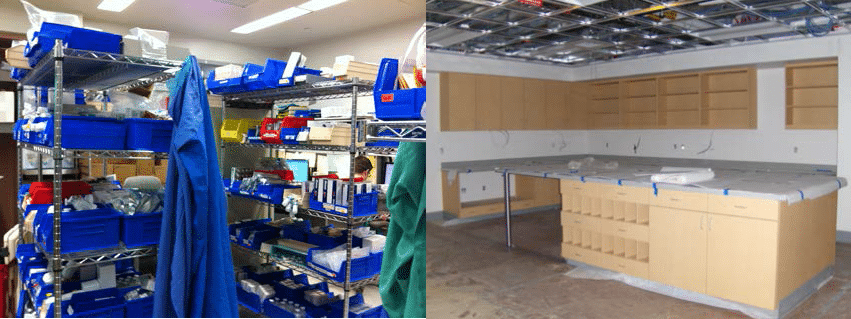 Figure 5-14. Existing pharmacy (left) moving into the new pharmacy (right).
Compared to the entire staff of the Children’s Hospital, the pharmacy had a relatively small leadership team and staff comprising of up to 130 members.
After the first focus group meeting, the participants distributed the interactive virtual prototypes of the pharmacy for other staff members to view (Figure 5-16).
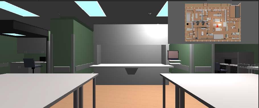
The pharmacy staff was able to familiarize themselves with the new layout using the EVPS pharmacy model for transition planning. 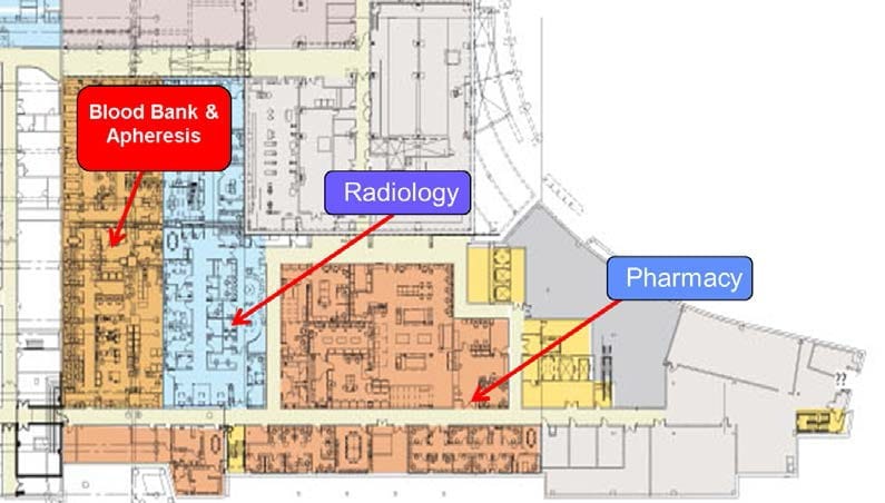 Figure 5-15. Pharmacy floor plan and snapshot of pharmacy EVPS.
5.5.1 Design Review Meetings
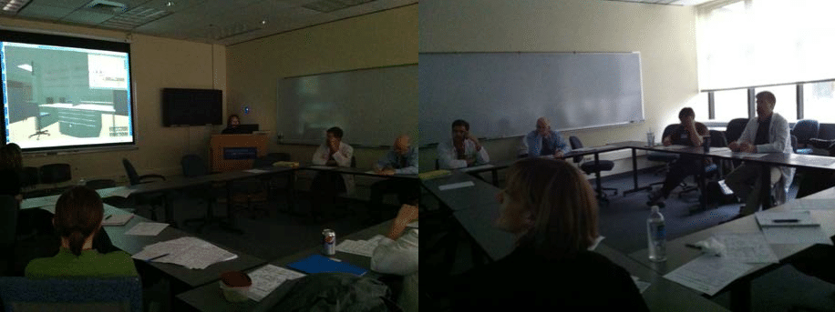
Two separate meetings were held with the pharmacy leadership team to discuss the scope of using the pharmacy EVPS for their transitional planning efforts. The researcher also attended and observed a design review meeting where 10 pharmacy leadership team members explored the EVPS model of the pharmacy (figure 5-17). The model was used to design the inner layout focusing on configuration and orientation of working spaces as well as detailed design decisions on storage shelves to plan and decide on future storage organization of the pharmacy inventory.

5.5.2 Findings
In conclusion, the staff was really relieved to be able to use an interactive virtual prototype of the pharmacy to identify workspaces and begin developing new work procedures. They felt that the EVPS was easy to navigate and had been using the prototype in internal meetings regularly. Although they had access to the actual pharmacy space under construction and staff was shown plenty of photographs and videos of the space, they still preferred the pharmacy prototype.
“It is easier to control where you are going and stop when you have to look at something. You cannot even do that in a video where you just follow along where the camera goes” In previous staff meetings, it was found that the pharmacy virtual prototype actually helped the staff identify that they would require a mini refrigerator in the compounding area.
This requirement was overlooked in plans and previous design review meetings and had not come to light till the staff had started using the EVPS for reviewing the design. Some of the drawbacks of the pharmacy prototype were inaccuracies in the modeling of shelves and other storage cabinets. It was found that some cabinets were missing entirely or had the wrong type of shelving depicted; e.g., closed shelving instead of open or slanted shelves instead of straight. The reason for this was that the changes had been made after the update of the model that was used to develop the prototype.
As the next step for using the EVPS for transition planning, the pharmacy staff wanted to have labels on different workspaces and shelves to depict what they were going to be used for. Another thing that would have been nice to see was whether drawers and storage was open-able or closed to be able to better plan for the move.
As a future consideration, the staff expressed that it would be nice to be able to simulate certain processes that take place in the pharmacy as that could be used to train new personnel on work procedures as well as help the leadership team design more efficient processes that would work in a new facility design.
5.6 LESSONS LEARNED
scale healthcare facilities within limited resources.
Dealing with Large-scale Models: Some of the challenges that arose with the use of large-scale models in the Unity game engine (ranging from 814 MB to 1.55 GB) for real- time visualization was to maintain minimal lag time and smooth performance during visualization. It is important to ascertain the level of detail of the model content available for developing the interactive virtual prototypes and determine if more detail and content is required or if unnecessary detail and model content needs to be eliminated to make the geometric content lighter and leaner. Finally it is of utmost importance to align the resources available to develop the EVPS with the proposed virtual prototyping scope. –
Defining Scope: Focus groups proved to be an effective means to elicit requirements for the development of EVPS. Brainstorming during the focus groups helped in generating innovative ideas on the future use of the EVPS. However, it is very important to define the scope for development and continuously review this scope throughout the design and development process while identifying the resources that can be invested. Feedback from the end-users during development ensures that the process is on track and that the EVPS will meet the ultimate goals of their design review. –
Identifying Stakeholders: It is also essential to ensure that the participants for the focus group represent a mix of department so that they can represent their unique needs. It was observed that the scenarios generated during focus groups strongly reflected the departments, roles and responsibilities of the participants involved. –
EVPS Application in Training: Although this research envisioned use of EVPS for design review with the end-users of facilities during the design development phase prior to construction, this case study demonstrates that real-time visualization using interactive virtual prototypes of healthcare facilities can be used at any stage of the facility lifecycle for design review.
Moreover, this case study also shows that apart from design review, EVPS can be very effectively used as an education tool for training, way finding and reducing the anxiety of end-users before moving into a new facility. Additionally, the EVPS can be used to design activities and working procedure around the new facility design as in the case of the pharmacy where the staff used the EVPS to determine their future workflows.
In conclusion, this case study demonstrates that the EVPS can be used effectively for collaborative design reviews and decision-making as exhibited during the pharmacy transition and move planning design review meetings. Interactive virtual prototypes of the pharmacy became an instrumental tool for pharmacy staff to seek clarifications in design and led to a better understanding of the new space.
Moreover, the pharmacy leadership team was able to leverage the EVPS as a tool to develop new work procedures that would be more befitting in the new facility environment. This unique application of the EVPS revealed added potential benefits of developing interactive virtual prototypes for healthcare facilities.
5.7 SUMMARY
This chapter begins with the description of the case of the Hershey Children’s Hospital and discusses the approach for research, data collection, analysis and development procedure for EVPS application. The pharmacy transition-planning meeting is discussed as part of the evaluation of using the interactive virtual prototypes for design review. Findings of this chapter suggest that even with large-scale healthcare facility models, EVPS can be developed and applied effectively. The next chapter discusses the evaluation of embedding scenarios in interactive virtual prototypes in more detail. ++++ Copyright 2013 by Sonali Kumar. All rights reserved. Thesis published on this site by the express permission of Sonali Kumar. Note: Under construction link to Chapter 6. ++++ Copyright 2014 by Sonali Kumar. All rights reserved. Thesis published on this site by the express permission of Sonali Kumar.